Tuesday, March 30, 2010

Another productive weekend


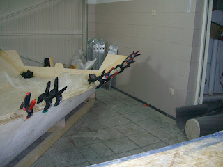
A picture is worth a thousand words. Hope the wives that might be reading this blog do not get too upset.

It is just so cool to see your own boat happening right in front of your eyes.
Come on, that is why all guys love spending a 'couple of hours' every now and then locked up in their dusty garage !

The Frankenstein Junior

That post is for Peter Ross and Ben. It is also for Tim who shared his thoughts on that with me.


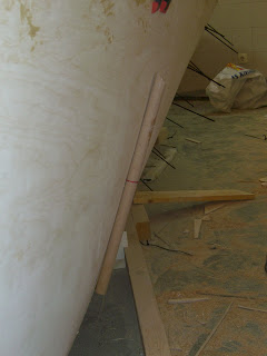
That is what I used to reduce the gaps at F53.5 which was definitely the biggest out of all frames. The cable outside of the hull is wrapped around a 30 cm wooden stick that progressively pushes the sides towards the frame as you crank that middle piece.


It worked really well and allowed me to close a good part of the existing gap in a pretty uniform and symmetrical matter, without creating any hollow on the outside part of the hull sides.


It still left me however with a significant gap which I will "twin" later on......

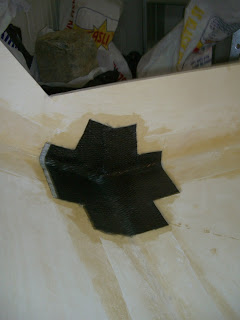
But know that I think about it, I could give it a technical twist and "twin it" with some kevlar cloth I have instead of using plywood strips..... Hum.....not a bad idea. Should be just as strong.


On the pictures below you can see the gap filled with epoxy/silica putty. I used masking tape on one side and "filled" the gap from the other side. As I am not leaving the zip ties in the fillet, I have also placed a few very small patches of fiber glass to hold the frame to the hull.
Once this filler cures, I will aplly a neat micro fillet, let it cure, than remove all ties, apply regular fillet and tape on fresh filet.

I have applied this technique for the hull and it gave me very good results with no need to sand.


RED OAK monster job


Well, I am not even sure it is red oak. The seller tells me it is white but from what I know and learned about it, its red !


Anyways, I am moving on. One thing is for sure : it is a tough wood !!! I had to go to the harware store to buy another blade for my planner. No kidding. Brand new electrical planner but the blades were gone after about 30 mns. Bought some better "made in Germany" quality blades and attacked the beast some more.


It went from this:


To this:

Yes I now. Not much to show...! I ll probably have to get some more blades to finish the job but at least I have started what I had postponned until now !

Hull panels adjustments and stringers


Spent most of my Sunday reworking the stiches on the side panels at almost all frames. When at looked at thme carefully, I noticed that they were all too tight. So as other builders suggested, I took my time to avoid any hollow on the hull at frame level.
First I cut off all ties that were visibly overtight. Then, I place new ones, tighten them carefully, one by one, using a straight stick against the outside of the hull to make sure no hollow was left.

I used that stick horizontally and vertically on side hull surface to check for concave areas (which is what you want to avoid). The objective was to tighten in order to have the closest to a flat surface but still leaving a slight overall outward buldge. Worked out great. Hull sides look fine from outside


The issue doing this meticulous job, is if you go a notch too tight on the zip, you create a hollow AND since you can't release the zip tie....your only alternative is to cut it off , replace it with a new one, tighten slowly, check for hollows with the stick, and on and on ....
Took me about an hour to redo the whole thing
As a result, I ended up loosening a lot of previously overtight stitches. I was left with some minor gaps (f 124) for which the colloidal silica fillet will be enough, but also some much larger gaps such as at f53.5 (as everybody else) for wich I might sister, brother (Ben's trade name) or even 'twin' (my registered trade name) a piece of ply. "Twining" would mean add a strip of plywood on both sides of the frame....We will see


I also had time to make some nice looking stringers. I really think that what Chad (http://i550knotracing.blogspot.com/) has achieved on his boat is state of the art. I mean his boat frame looks so cool. So just for the fun of it and because I really think they look awesome, I did some similar stringers for the last compartment between f214 and f169.5.
Not exactly as Chads, but good looking enough for me. No real functionality but pleasant to the eye and since I am really enjoying the building process , I treated myself with a little eye catcher that will soon disapear underneath the cockpit sole... The fwd stringers between 169.5 and 124 are more conservative with plenty of round cutouts. I used the rule of thumb that was given by another builder : 1 diameter space between holes and at least 1/2 diameter between holes and edges. It is simple to apply and gives a good balance to the final piece.

Monday, March 22, 2010

out of the blue


Just had to post this one.


My back hurts from all the fileting and taping, my hands are bruised and swollen from all that cable pulling, İ am caughing because of all the dust in my garage, but man, do İ LOVE this building process !!! My wife, who doesn't even dare getting close to my building nonsense, thinks İ am loosing it...But there is nothing more rewarding than seeing that İ am actually making something pretty neat out of all this wood. And that is without any prior construction knowledge.
Pretty rewarding feeling !!!

So thanks Chris for the project,thanks Tim and Susan for making it available to all of us, and thanks to all those pioneers and more experienced builders who are always ready to answer any question. This is a really great community.


how to find the side locations for frames

İn a previous post İ described the method İ used to mark all frame location on the bottom hull. As a summary:

-draw a center line on your bottom hull from bow to transom
-pull a string across the length of your boat from bow to transom. Make sure this string is fixed at the same height at bow and transom. You want it to be paralel to the water line.
-mark all frame placement on this string
-use a plumb at each mark (İ use a thin string and a simple drop like fishing weight) on the string to indicate you the exact location on bottom hull panel
-draw a perpendicular line to the center line at each plumb mark.

You now know where to align the bottom of each frame.

To know where the side of the frames go, simply use your plumb again to level your frames straight. İf the bottom of the frame is on the hull line you drew and your frame is leveled straight, then the edges of your frames should be at the right location.

One issue İ had however is that some of my frame had a bit of warp and although the bottom was right on the money, the edges were not where they were supposed to. To correct this, İ used a simple long straight 1" x1"wood stick and clamped it to the top of the frame, across the hull width (from star to port) No more warp, frame edges pointing were they were supposed to.
Final check was using the Beckwith String Method, which is excellent. Just attach a string a the bow and measure the distance from bow to frame edge on one side. Keep the measurement and move to the other side pulling that string along with you. The frame's other end should be exactly at the same distance from bow.
Repeat the whole process a few time (bottom alignment,frame plumbed,Beckwith method) making smaller and smaller adjustments and in about 10-15 mns you have a pretty accurate position. Mark this position along the inside panels and on top of sheer clamp. Proceed with making all holes, pass the zip ties trough, tighten carefully and progressively making sure you have no hollows.
Voila !!! Frames are in place
On the left picture , if you look carefully, you will notice the center line drawn on the bottom panel, the main guide string running from bow to transom, and the little plumbs made of string and washers I have used to insure all frames were leveled at their correct location .


Detail of of little plumb hanging down from main string. Everything seems to be pretty symetrical and well aligned.

zip tying frames

Except for frame 18 which İ placed and filetted a week ago, İ seriously started working on the frames the day before yesterday.

The initial idea was to start from bow F18 to transom F214, just as recommended on the builders guide, but after İ hit on F53.5 İ decided to stop and analyze the whole thing better. After a little observation, thinking and experimenting with my hull, İ decided to invert the frame zip tying process and start from the end.

The reason is that İ had a gap ( between side panels and frames that is) at ALL frame locations without exception. Trying to close out this gap on forward frames proved to be a tough challenge. İ believe that the tension on the side panels up front at the bow is much greater that closer to the transom due to the compound curve fwd F18. Aft, the panels are pretty much straight and flat and easier to move. İ also imagine that placing the aft panels first might just as well put the whole side panels into position and release some of that forward tension.

So İ zipped 169.5 , 124 , 110 and prepared 89 (cut out upper corners for sheer clamps and bottom corners for filet spacing). Overall it went really good and İ was able to zip tie all frames tight to the hull without leaving any space or creating any hollow. The only exception right now is frame 169.5 wich İ overtighted and slightly bulged inwards creating that undesirable shape. İ will unzip it and do it again.

For all frames, İ was very carefull to how much İ could push the panels inward, towards the frame. İ proceeded slowly , tightening each zip tie progressively and always checking with a long flat ruler that the side were not caving in. Took some time but worked great.

Frames plastic surgery

After reading was has been recently discussed in the forums and consulting with some fellow builders (thanks to Ben, Tim, Tom, Kevin, Jeff..), İ decided to do some important changes on 2 frames.
First frame 89 was beef up, but İ mean "seriously" reinforced :
1-İ doubled it up, which means the whole frame is now 1/2 inch instead of the 1/4 the plans called for.
2-İ redrew the upper arch to 2 full inches instead of the 1 inch specified in the plans
3-İ reinforced it further adding another strip of plywood going all around the arch until right below the lightening holes. İn other words, the top arch is now made of 3 layers of 1/4 plywood....

That should be strong enough to widsthand any load on the mast /compression post.


Second, İ did aesthetical surgery on F124 and did what other long cockpit builders did : İ widened the cockpit area at the cabin entrance.

The original drawing called for a very curvy cockpit getting closer to the cabin area. İ personally believed that a widened cockpit up front was a better solution for looks as well as for crew placement and since this is a homebuild project, İ took the risk to alter what İ believe could be eventually improved.
So basically İ left the upper sides of F124 with exactly the same dimension as F169,5, that is 16,64 inches and reinforce it to compensate the "hole" that was left over. İndeed, cutting frame 124 leaves the side panel very loose, flimsy and unsecure because you end up running into thin air when cutting trough the bunk's cuttout. İ did not have enough plywood panels left and frankly, was kind of lazy to recut the whole frame. So İ opted for reinforcing the frame and for that matter İ did exactly what Tford did on his boat. Compare pictures and you'll see what İ mean. Tford, you be proud that your solutions are replicating throughout the boatbuilding community. İ owe you that one ! Good for a beer if we end up sailling together !


A minor tweak İ added to Tford solution is that instead of laminating together a 2x 1/4" reinforcement and then epoxy it to the frame, İ added one reinforcement on each side of F124 and laminating the whole thing all together like a sandwich around the original frame.
The result was good and seemed to be very strong.


Sunday, March 14, 2010

Marking frames location on hull bottom

The first thing I did was to draw a line at the exact center of my bottom hull panel, running from bow to transom. Actually this had been done previously and was mandatory for frame placement.

Then, using a dark colored marker, I carefully marked the string I had running from the top of the bow to the transom at the exact frame location.

Finally, I simply used a another smaller piece of string with a fishing weight attached to it (it is called a plumb) and let it hang from each mark I had previously made on the main fwd-aft string. I marked the place where the weight was hanging on the hull bottom and then drew a perpendicular line to the center line on the hull.


The result was a clear and precise mark for all of my frame placement. And yes, I will not lie, I got inside my hull to draw all frames locations.....It did not complain nor did it make any unpleasant noise.... Good.


Then I proceeded and placed frame 0018 on its line drawn on the hull as previously described. İ made sure it was straight with my plumb and double checked that the distance was the same from each upper corner of the frame to the middle of the bow piece.
Once everything was good, I zip tied it and used the same micro filet I had done before for my hull panels.


No big issue exept for the notches at the top of the frame to accomodate the newly installed sheer clamp.
As soon as the micro filet cure, I will cut off the zip ties, lay down another larger filet and tape alltogether.
I am really happy to start have reached the point of placing the frames. I know it is a delicate fase and very important for hull symetry and bottom shape (convex from bow to stern and forward V).


I believe I will be more relaxed after finishing that important step of the building process. Then it is all reinforcement and closing.......There is however a long road before I get there.


Sheer clamps are good !

Woke up today and confirmed that the sheer clamps had not ran off. They were steady and firmly in place where I left them yesterday :)
So I removed the screws and the small plywood tab I used on all joins, grabbed my eletrical planner set the blade to a medium depth and started shaving all of the excess out sticking out of the plywood edges, mainly towards the transom where that 45 degree was almost sticking straight up !
After 20 mns of loud noise, the sheer clamps were pretty smoothed and leveled. Next step.

Sheer clamps, at last !


Wouah ! That was a headache. Seems simple but those sheer clamps really gave me a workout !

First concern was that I think the profile İ used (2"x2") was too bigç so they ended up to thick and too strong, therefore somehow reluctant to assume their shape nicely following te curve of the side panels.

Second concern was the 8:1 scarf... Try that on a triangle profile !!! You end up with a sword like pointy piece of wood that sure does not look strong...

So I decided to go a different .......and pretty complicated way......which İ don't recommend anyone to follow !

First i decided to go with 3 segments for each sheer clamp. The building manual mentions not to make the sheer clamps out of more than 2 segments but İ figured that since they do not have any real structural function and since the forward and the aft segments are almost straight, İ might as well go with 3...Another element for that decision was that İ wanted to avoid having a scarf right in the most curved part of the hull, right where the pulling forces on the sheer clamp are greatest
So İ used one almost straight segment at front, a curved segment for the larger hull panel curve and another almost straight segment for the final part of the hull. All joıns were out of the curvy part and İ thought İ had it
Second mistake is that since I did not like the look of the scarf, I decided to butt join my sheer clamp .
I reinforced the butt with strips of carbon............ but that did not work ! Looked pretty good at first but as soon as I force the sheer clamp in place, too much force was applied to the joins and they cracked. Had to work them over and add temporary strips of ply to make sure they would hold.

So by the end of the day I was still working at them but managed to epoxy them in place using many wood screws and clamps.
I then fileted and taped them in place. I was pleased with how they looked at the end but for any builder who has not gotten trough this stage yet, one word of advice: if you can, stick to one long, single piece of wood for your sheer clamps. And if you have to join parts, scarf them (butt joining doe not work) and dont make them out of more than 2 halves. 3 is nonsense. My next hull will be better ! :)
So I will have to wait tomorrow for the resin to fully cure to remove all screws, clamps and plywood strips to make sure everything is really holding strong......

I will keep my fingers crossed !


(Lots of clamps needed ! I used 10 clamps plus about 6 screws on each side. Could have easily used as mnay has 20 clamps per side if I had them handy.)

Next steps for me tomorrow:
-level off clamps with eletric planner
-mark correct distance of all frames on hull
-place frames

How to do a clean taping without any help

Here is a little trick that might help some builders.
To obtain better results for taping the sides to the bottom panels, I used a single 5,50m long tape. As mentionned in an earlier post, I cut this tape from a larger roll of fiberglass.
So the first trick is , before you cut the tape out of the roll, lay down masking tape and then cut on top of the masking tape. This will allow for a clean cut without loose fiber cloth strings.

Leave the masking tape on and laminate with it facing DOWN. You will get a very clean lamination, no fibers wandering around or stricking to your gloves which can actually end up being a real nightmare.
Just do not forget to trim it off once the resin has startd hardening but is not completely cured. Kind of halway trough.(green stage)


The second trick is if you are working alone on your boat, which is my case 100% of the time, roll your cutted taped on anything handy and use this support with your rolled tape to laminate your hull seams.


Just unroll it progressively as you are laminating your hull.
In my case , I used a simple cheap tube of insulation foam which was leftover on my floor garage.
This technique helped me tremendously.

Carbon strength- overbuilt ?

Then, since I was still concerned about the strength of that seam (remember I could never get the panels to fully join together without getting a much narrower hull forward and a very pronouced V bottom) I decided to reinforce it with one layer of carbon fibre coming all the way
down from the top of the bow.
The end result was so nice that I also reinforced the side panels/ bottom hulls junstion as well as the transom / side panels / bottom hull.


Might be over the top but will certainly add more forward-aft rigidity. Can't be all that bad !

Time to remove zip ties

After letting the micro filet cured, I carefully removed all zip ties. The hull was holding together only by the tiny fillet... but looked good.
I apply a larger filet over the already cured small one and proceed taping while the larger filet was still wet. Since I could not find tape of the right dimension here in Turkey, I ended up cutting the tapes from the large roll of fiberglass cloth I purchased. However, in order to avoid the mess of loose fiber strings gluing allover, I used masking tape on all sides of the fiber tape I was cutting and laminated the whole thing with masking tape (facing down) and all (firstpicture)
When the resin started curing and reach green stage, I trimmed the masking tape off with a wheel cutter. Clean result, no mess at all. (second picture)


And by the way, I laminated it all from outside of the hull...! Let me tell you from personal experience that you better have a solid lower back if you want to work for long periods of time in such an ackward position.


After the side panels tape was cured, I proceed with the middle hull seam. I admit that I ended up laying down inside the hull to finish off that seam. No way I could reach it from the outside of the hull.
The end result, however, was pretty clean, no excess resin.