Friday, July 23, 2010

The keel plug

I am using a pink "Owen" insulation foam I found at my local hardware store for the keel plug.


I bought a block which is just 5cm thick which is perfect for all sections except the first 4 which needs to be 2,5 cm. For those thinner sections I used a thinner foam sheet which I glued in layers until I got approximatly the desired thickness.


Please refer to Kevin's (PipeDream) great post on keel plug building on the forum under Building > Foils > "Keel bulbs...info and how-to's".
There you will also find a pdf from Chad Knot racing which clearly shows what are the 20 section. If you are not carefull you will end up with 19......just like I did !


Cutting the pieces out was really extremely straight forward.

First I cut out the templates I had printed one by one. I then used a marker to mark the contour of each piece on the foam blank. I marked the wide point line on each piece which gave me a usefull reference to align all pieces later. I used my jigsaw with a longer blade and cutted all pieces. Used a block sander to do minor adjustments since the pieces were cutted pretty precisely with the jigsaw.

Piece of cake !
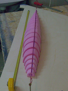


Than just to make sure they were perfectly aligned I pulled a string above the keel plug, across two screws that were placed at both ends of the plug.
Then looking straight down from above I align the widest point marks with the string. Not rocket science but it is simple and it works.


And just as a teaser of what's coming next, I dry fitted the cockpit sides. Those were cutted from o cardboard template I made but that is a story for future posts.


I am off to Brazil for 2 weeks of vacation....so the build is on hold until I come back !

Saturday, July 10, 2010

More kevlar !

I was not really in the mood lately for doing more lamination , but today I woke up feeling like messing up a bit with kevlar...!

As s matter of fact, I still had to work on the forward bunk support / stringers and decided to reinforce them with kevlar , just as I did all the others.

Except that this time I was a bit more carefull cutting the strips... It is important to note that I am not working with tape, but I am simply cutting strips of cloth out of a large roll.......and that can be very messy if you are not very cautious ! Kevlar cannot be compared to fiberglass, which is a pleasure to work with ,or with carbon which is simply the best and easiest I have worked so far.

The kevlar cloth I have is dificult to cut, dificult to handle and dificult to laminate.

So this time my strips were cut very straight, carefully following the thread, and I had very few loose strings. That made a big difference !

I laminated the kevlar directly on the stringers, layed on top another 6 ounce fiber glass tape, and finished it off with a strip of plastic film (the same stuff I used for my keel). Squeege once again came to the rescue to make everything smooth, flat and without any excess.

The end result was very good, much better than before. The edges of the kevlar are thin and flat, no bumps, no loose strings.

This result got me motivated to use kevlar on the sheer clamps and the hull's center seam. This was actually the reason why I bought kevlar in the first place, but I ended up kind of changing my mind after the initial hard experiences I had laminating the stuff.

I guess now I am learning how to deal with it and I should be able to do allright on the hull without massive fairing afterwards.

We will see....

Larger glueing surface for cockpit

After Ben's long description on his blog of how it felt diving into the interior of the beast to glue the cockpit floor, I have been having nightmares.......Well , almost !


But there is NO WAY I will dare try to tape from underneath. Hey, this building should pleasurable and since I am a bit claustrophobic, that is simply out of the question !


So I decided to increase the bonding area of all frames to cockpit junction. I did just like Jeff of Alchemy and epoxied a 2cm x2cm split in half wherever needed AND on both sides of the frame.


So in total I will have 2cm (cleat on one side) +0,6 cm (ply of frame) + 2cm (cleat on other side) =4,6 cm.


That is almost 2 inches of bonding area. Should be enough and no matter what, it sure beats taping from underneath..........AAAAAAAARRRRRRRGGGGGGGGGGGGHHHHHHHHH!!!!

Are you good at Trigonometry ?

I am not !


But it sure looks like some kind of a dificult trigonometry experiment...

Actually, I just applied wht Josh-Shazza told me to do to find the exact location of the chainplates. It works perfectly. Thanks dude.

Ben-Booger also helped me out with another way of finding the angle but since I am going for the same alu rig as the Aussies, I decided to got with the exact same angle for the chain plates and therefore the same method to place them.

If you carefully look at the picture , you will get what this method is all about. It is really straightforward for a 22,5 degrees angle.


First of all you should have a staight and plumbed F89 set at 90 angle from your boat CL. Thanks God mine was...!


1-I placed a string across the boat from stem to stern.That is the pink string on the photo.

2-I dropped a plumb right in the center of F89 where the compression post will be. That gave me an intersection with the pink center line string.

3-From that intersection (which was squared vertically, plumb /CL) I projected a 90 degree angle onto the side of the boat. That hit the inner edge of F89. I marked that point and measured the distance to the center line string.

4-I measured the exact same distance from the intersection point on my CL string. By doing so I was now with 2 sides of a perfectly leveled square.

5-I then pulled a string from those two points to "draw" a 90 degree triangle.

6-Marked that string right at its center and pulled another string from the squared angle, passing on that mark ang going all the way to the sheer clamp. My 90 degree angle triangle was now divided into 2 equals 45 degree triangles.

7-I divided that triangle once more using the same method, pulled it all the way the the sheer clamp and ended up with a line at exactly 22,5 degrees from compression post.

Et voila !

I now it sounds a bit complicated but that is because I suck at explaining ! Josh email to me was much clearer.
Anyways, it is easy and since a picture is worth a thousand words, I will say no more....


Maybe just a last one : I did exactly the same thing for the other side. Then, just to check how symetrical my hull is, I measured the distance from bow to chain plate gusset mark on on side and compared it to the distance on the other side. Spot on ! I could not be happier !!!